SEGA Mega Drive / Genesis hardware notes
This is a mirror from https://docs.google.com/document/u/1/d/1ST9GbFfPnIjLT5loytFCm3pB0kWQ1Oe34DCBBV8saY8/pub
By Kabuto
Written by Kabuto of TiTAN during the development of Overdrive 2
Version 1.5
- Foreword
- The bus system
- The YM2612
- The VDP ports
- Picture size
- H/V counter values
- V28/V30 tricks
- Precise details of sprite rendering
- Memory access pattern
- Effects of 'disable display'
- Timing tricks with the H40 mode flags
- Address mapping
- 128 KB mode abuse
- Mode 4
- Access timing
- DMA speed
- S/H
- The mighty debug register
- Debug display mode (combinations of bits 8,7,6)
- Debug register write glitches
- Plane masking instability
- Change list
- Footnotes
Foreword
This is the first of a series of documents about Overdrive 2 and its development.
This document specifically contains what I figured out about the Mega Drive hardware during the course of 4 years. Nearly all of this has been through running my own tests and guesswork, some information was gathered from the web and from discussions with others (I tried to cite everything correctly).
I did not include information that is well documented elsewhere (e.g. how the CPUs behave).
I hope this will be helpful for emulator and demo developers. And please fix your emulators, even for not so obvious issues (e.g. music playback)! My music player relies on the Z80 getting delayed for ROM accesses and plays samples too fast and distorted when it’s off, just using a default value of 3.3 should already do the trick here.
Regarding all the VDP tricks used, these are of different complexities. Some (128k mode) are probably just a few lines of code, others (VDP debug register) maybe 100 lines of code; the most difficult thing to get right will probably be the twisters, they require exact DMA and FIFO stall timing, otherwise they will break. Also, when debugging overdrive 2 effects, please ensure that the music is still running properly, if it isn’t the Z80 might as well be running around in the mapped ROM area and thus causing lots of 68k delays, breaking effects. At least that happened to me many times during development when I accidentally broke things.
I need to thank all those people who pointed out that there is something (“$c0001c does weird stuff”) and spawned my interest to dig deeper, and those who encouraged me with their claims of something being impossible ;)
The biggest part of this document describes the VDP since that’s what I spent most time on. Since all other parts are so much smaller I put them first.
If you find anything wrong or have questions just post a message on the gendev forum or in #titandemo on EFNet.
Happy coding!
- Kabuto
The bus system
When the Z80 accesses ROM the bus arbiter needs to pause the 68k, let the Z80 finish its request, then unpause the 68k again. Since all those components run asynchronously timing is barely predictable, also if the 68k is just about to access the bus itself it finishes its own access cycle first before releasing the bus. This typically means that the Z80’s 68k bus accesses will be delayed by 2 to 5 cycles. IIRC reads and writes behave exactly the same way. The average Z80 delay is around 3.3 Z80 cycles, whereas the average 68k delay is around 11 68k cycles.[1]
If the Z80 tries to access the bus while the VDP is doing a DMA from RAM/ROM or the 68k is halted because it tried to read from the VDP while its FIFO is empty or write to the VDP while its FIFO is full it has to wait for that to complete first.
IIRC If the Z80 tries to access ROM while the VDP is doing a DMA from 68k RAM this can lead to corruption of RAM contents due to glitchy signals on the address bus (similar to the C64’s VSP bug).[2]
The 68k is a bit slower than expected because something on the bus steals 2 out of every 128 cycles. This is visible when measuring the bus because every time 128 cycles have passed the next bus access is slowed down by 2 cycles. The slowdown even affects the Z80 if it happens to hit its ROM access. Interestingly if this hits when the 68k is writing to the VDP (no matter which port) then the slowdown doesn't happen. Tampering with internal registers didn't seem to affect this at all. And this doesn't seem to be the RAM refresh logic since RAM accesses get their own further slowdowns. (I did not try to investigate this further, I just noticed that code accessing RAM instead of ROM is slightly slower.) Maybe it's a leftover from development kits that are based on DRAM cartridges that need to be refreshed as well. After all these slowdowns the 68K seems to be running at roughly 480 cycles per raster line instead of the theoretical 488+4/7 ones.[3]
I did not see hints of those slowdowns during DMAs, probably the VDP accounts for that itself by not fetching fresh data during DMA for 2 consecutive cycles whenever it’s spending 1 internal cycle on VRAM refresh. For fast DMA this means that 10 slots are lost every rasterline (these are limited by how fast the VDP can fetch fresh data), for slow DMA (to VRAM in 64k mode) thus only 5 slots are lost (limited by how fast the VDP can write to VRAM).
The YM2612
YM2612 registers $30..$FF are special as they only exist in a shift register that rotates all the time, but this also means that the YM2612 must wait until it reached the desired register before it can overwrite it. That’s what’s limiting the maximum write speed to ½ the duration of a YM2612 cycle, or 33.6 Z80 cycles. Probably slightly more due to latching overhead. I.e. after writing a register value one needs to wait that long before writing the next register’s address.
The YM2612’s busy flag is useless as already documented elsewhere.
It’s not possible to reliably write both register number and data with a Z80 word write, that seems to be too fast for the YM2612.
The YM2612 samples the PCM register once every cycle. The point in time when that happens differs between MD1s and MD2s I tested (and is different again in emulators, but unfortunately I can’t give any precise values here, I’d have to dig for my test code), it also seemed to be more stable on MD1 and varying a bit or sampled for longer than just an instant on MD2.
I tried to account for both in my music routine to keep jitter down to an inaudible or at least barely audible level. And beware of the music routine in general, I developed it from scratch to support 26 kHz sample playback with nearly no jitter, and for that used every available trick. Also it reads the VDP’s V counter, make sure your emulator supports this when there are music issues.
The DAC works a bit differently in MD1 and MD2. On MD1 it just outputs a short pulse for each voice, one voice after another in a cycle, on MD2 it holds the value for quite a while (but still just a fraction of that voice’s slot which is 1/6th of the YM2612 clock (about 53 kHz)). Maybe the YM2612 allows for replacing the DAC value for as long as the DAC is being held which would explain the behaviour seen on MD2s.
To measure the audio quality I wrote an analysis tool that measures a number of parameters:
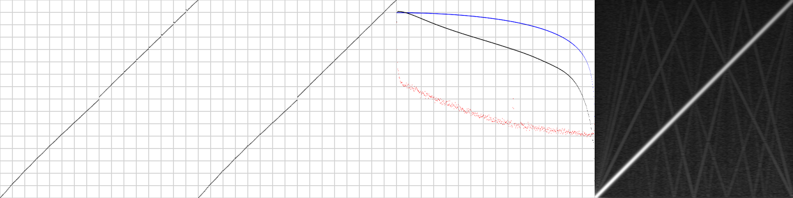
The leftmost 2 diagrams are voltage levels of the DAC, first one with the 9th DAC bit set to 0, second one with that bit set to 1 (that bit is normally set to 0 when playing PCM). As you can see there’s quite a jump of 3 samples between $7F and $80 (exactly in the middle) and a few further values are quite off too.
The 3rd diagram measures frequency response from 0 to 26391 Hz. Blue is expected outcome, black is measured and red is noise floor. The way I measured this (playing white noise and phase correlation with measurement) allows telling apart signal and noise quite well.
The 4rd diagram is the frequency response of a sine sweep. A bit of nonlinearities here, but nothing to worry about IMO. These might be due to DAC nonlinearities already.
Now, for comparison, a MD2:
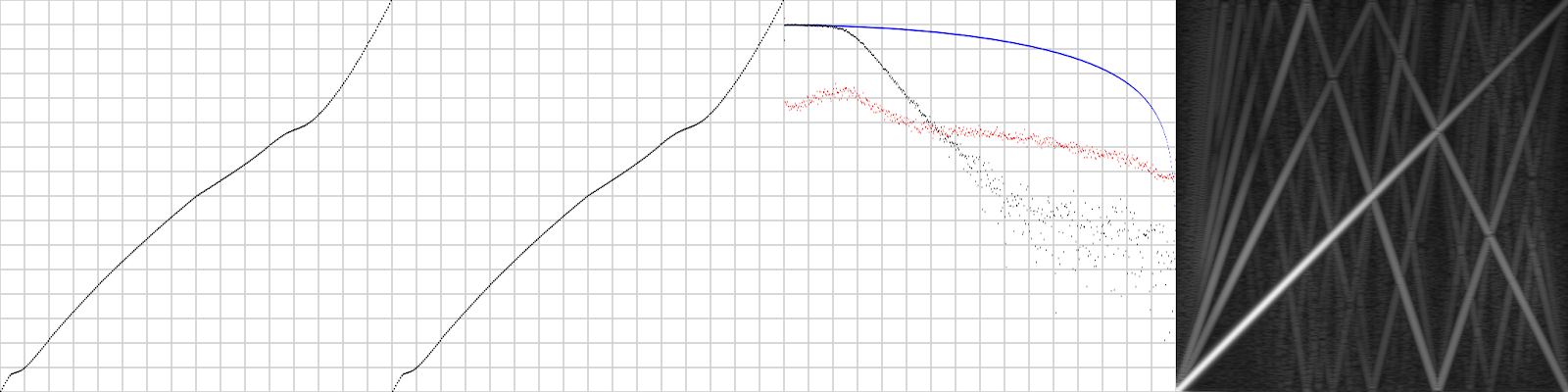
Those jumps in the DAC are mostly gone and longer DAC output should in theory mean lower noise floor, but… the amplifier circuitry destroys it all, introduces severe nonlinearities, and instead of the MD1’s 1st order filter there’s a 2nd order filter for no obvious reason. Distortion is quite high too, very well audible.
The MD2 sounds noisy, muffled and heavily distorted, I clearly prefer the MD1. I measured a few more MD1s and MD2s but their responses look pretty much like those shown here.[4]
I also tested the “loud PCM” debug bit. It amplified the volume around 5-fold on MD2 as expected and about 30-fold on MD1 (which typically leads to heavy distortions as the MD1’s amplifier does not expect to see anything louder than all 6 FM voices being played at once at maximum volume).
The VDP ports
The VDP’s command port is directly connected to its internal address buffer without any latching (or rather, the respective half thereof; after writing the 1st half of an address the next write will go to the 2nd half unless you e.g. write to the data port first). However depending on the value written certain actions can be triggered:
- if the topmost 2 bits of the 1st half are 10 then this is a register write, the command port is not directed to the 2nd half, instead a register write is initiated (and executed after the next internal VDP clock = once every 2 pixels). So this way the command buffer serves as a latch.
- if bit 7 of the 2nd half is set this initiates a DMA.
The address buffer is incremented after each VRAM/VSRAM/CRAM read or write (by adding the value from register $f). When writing a value to the VDP’s data port (or the VDP does that internally through DMA) both value and current address are appended to its internal FIFO, so the address is incremented immediately even if the VDP could not actually write the value to its memory yet. And if the FIFO was full then the CPU is blocked for a bit first. In either case this means that the CPU could not potentially access the control port while the VDP is incrementing it internally and cause any trouble… except for 2 corner cases:
- DMA fill/copy: these run internally in the VDP and the CPU is not blocked from accessing the control port. Sega already warned about leaving the VDP alone while such a DMA is ongoing.
- Setting up the VDP for read: after writing the read command the VDP will immediately fetch the desired value from its internal memory into a buffer (same FIFO? or separate?) for the CPU to read; once the CPU read that value the VDP reads the next value. And after each read it increments the address register. But especially when reading from VRAM (2 reads needed instead of 1?) and during active scan (VDP will need to wait until the next access slot) if the 68k immediately writes to the command port after reading a value from VRAM through the data port this can cause a conflict because the VDP will only increment the address after having fetched the next value; funny effects occur if the 68k tried to write to a 68k register, typically leading to the register number and value being ANDed with the address after increment, or with the address before increment and then incremented, before being used as new register number and value to write to. (Since a register write was already triggered by the 2 topmost bits it doesn’t matter if ANDing alters these 2 bits, the register write will still occur.)
Further notes:
- It is possible to make the VDP do a VRAM read DMA. Of course that does not make much sense and it does or does not crash depending on circumstances...
- The claim I read elsewhere about CRAM DMA that's wrapping around the end of a 128 KB ROM “page” aborting automatically is definitely wrong.
- Writing to register $17 with bit 7 clear (highmost byte of DMA source address, pointing to 68k address space) seems to set a flag that's only reset when doing a DMA. Setting a VRAM address (for read or write) while this flag is set will crash the MD.
- Reading $C00018/$C0001C the usual way (move.w addr/(reg), dX) returns the following opcode as the 68k prefetches it before doing the actual read access in this case. Just every now and then, probably when there are bus delays / z80->ROM accesses, a value of $FFFF is read (due to bus pull-up).
- The upper 6 bits of the status register are also determined by data left on the bus, i.e. typically the next opcode’s upper 6 bits, sometimes just “1” bits.
Picture size
Normally an image consists of the following raster lines:
PAL: 38 border, 224 picture, 32 border, 3+3+3 sync, 10 blank = 294 picture/border + 19 sync/blank = 313 total
NTSC: 11 border, 224 picture, 8 border, 3+3+3 sync, 10 blank = 243 picture/border + 19 sync/blank = 262 total
(in 30 row mode the picture gets 8 more lines from each of the borders, i.e. 16 total)
The horizontal image size is 13 additional left border pixels + 14 additional right border pixels. Probably alike for H32 mode.
Also, in H40 mode the VDP slows down its clock for a number of cycles during HBlank (32 pixel clocks according to my oscilloscope tests) - starting 24 pixels after the right edge (or 10 after the last rendered pixel), so doesn't affect visible pixels. It's just the actual hsync/colour-burst area that seems to be affected.
Vblank is switched roughly 32 pixels before hblank starts. This means that the last hblank raster line has that number of valid pixels displayed at its end while the same number of pixels is missing from the end of the last raster line before vblank. Jorge suggests that this probably happens because the VBlank signal directly affects output and does not have to go through the long pixel pipeline first, and in interlace mode, for odd (or even?) fields the blanking at the bottom of the screen starts in the middle of the raster line, but the unblanking at the top still happens in the same spot.
All blanking in HBlank and VBlank is done after palette lookups, so not even CRAM dots will appear in there.
H/V counter values
(Source: https://gendev.spritesmind.net/forum/viewtopic.php?t=768)
| Mode | H32 (RSx=00)
| H40 (RSx=11)
|
|---|---|---|
| HCounter progression | 0x00-0x93, 0xE9-0xFF
| 0x00-0xB6, 0xE4-0xFF
|
| VCounter increment | HCounter changes from 0x84 to 0x85
| HCounter changes from 0xA4 to 0xA5
|
| HBlank set | HCounter changes from 0x92 to 0x93
| HCounter changes from 0xB2 to 0xB3
|
| HBlank cleared | HCounter changes from 0x04 to 0x05
| HCounter changes from 0x05 to 0x06
|
| Video | PAL V28 (M2=0)
| NTSC V28 (M2=0)
| PAL V30 (M2=1)
| NTSC V30 (M2=1)
| |||||||||||||||
|---|---|---|---|---|---|---|---|---|---|---|---|---|---|---|---|---|---|---|---|
| VCounter progression | 0x000-0x102, 0x1CA-0x1FF
| ||||||||||||||||||
V28/V30 tricks
The picture always starts at raster line 0. When switching between V28 and V30 the only thing that changes are the raster lines in which to switch vertical border / vblank / vsync as you can see in the table above.
When switching to V30 within active scan and back to V28 after line 224 but before line 240 then the VDP will “forget” to start the vertical border and keep display active all the time. (This is similar to C64, except that while the C64 tests the border flag twice per raster line the VDP tests it constantly, so having V28 active for a single VDP cycle during line 224 or V30 for line 240 will start the border.) The resulting picture is still stable since vblank still works normally. This trick works on NTSC too, allowing for 243 instead of 224 vertical lines without a rolling picture.
Sprites and HScroll work as expected in the vertical border area (though just the lowmost 8 bits of the raster line are used for HScroll lookup), also both planes work normally unless a plane size of 256x1024 pixels is used because the raster counter just uses 9 bits so graphics in the upper border will be vertically off by 512 pixels. (And this affects raster line 511 too which will be explained below).
When opening the vertical border this way HIRQ runs continuously and is not reset before the start of each frame.
Precise details of sprite rendering
General
The VDP has an internal sprite cache that caches the Y and size/link fields of each sprite in order to quickly determine visibility of sprites without having to access VRAM. This is implemented as a write-through cache - the moment a write to VRAM occurs the VDP checks whether it goes to the current location of the sprite table, and if it does and affects an Y or size/link field then the respective cache table entry is updated. And this is the only way of updating the cache, moving the sprite table address will NOT update cache contents (so contents of the cache and underlying memory will differ). Also, this mechanism is sensitive to the entire 128 KB address range even in 64 KB mode, so when setting bit 16 for the sprite table address but not for the Write/DMA target address (or the other way round) the sprite table in memory will get updated but the cache won’t.
TODO what happens to the sprite cache when writing to odd addresses (64 KB mode)?
Phase 1
2 H-borders before the raster line to be rendered the VDP checks all 80 sprites. It iterates over the cached portion of the linked sprite list (sizes and Y positions) using the link fields and identifies the first 20 sprites that are visible by examining Y position and vertical sizes. The VDP iterates a maximum of 80 (64) sprites, starting with sprite 0, following the link attribute, potentially looping (if there's an endless loop) and rendering sprites multiple times (which normally has no actual effect, though), but a link attribute of 0 makes it stop scanning the list further instead of re-evaluating sprite 0.
Every VDP cycle 2 sprites are checked, that means one sprite every pixel. This scanning seems to start 6 cycles after the first sprite tile fetch and continues for exactly 40 cycles. No sprites are checked while display is disabled, also during the access slot in the middle of sprite fetches probably no scanning is done either. Modifying the sprite table during this slot does not affect the first 34 sprites but only the 46 sprites after those. (It is difficult to exactly determine when those checks occur since they only use cached data, evidence gathered so far includes this access slot and display disabled behaviour, including disabling display for the very first sprite tiles fetches for which the number of available sprite slots is not reduced. Still there are some discrepancies such as why the numbers of access slots lost due to disabled display are not exactly identical for phase 1 and 3 when they should be.)
The outcome of this phase is stored in a shift register with 20 slots containing numbers of sprites deemed to be visible - as long as the register isn't full yet, every time a sprite is determined to be visible it's shifted into the shift register from the right.
Phase 2
1 raster line before the VDP iterates over the visible sprites and fetches their X position and tile info. If there are less than 20 ones visible then they're checked late. For unused sprite slots sprite 0 is accessed but the data read is discarded. Furthermore, vertical position and size are fetched again from the sprite cache as well so they are evaluated twice per sprite and raster line.
The VDP computes the address of the sprite row and stores it (14 bits) together with further info fetched (9-bit sprite X position, sprite size, palette, priority, horizontal mirror flag) in another 20-slot cache (TODO that cache has 34 bits per entry but so far only 31 bits are used), however this time it’s not a shift register but an indexed cache, starting at 0.
The VDP just considers the lowermost 5 bits of the difference of sprite Y coordinate and raster line and adds it to the address of that sprite column’s top. This matters if the sprite’s Y coordinate is changed after it was determined to be visible in phase 1 - it is always rendered during this phase even if its new Y coordinate is no longer in range as if it was always 32 pixels high and just repeating after that. This for example means that sprite column 0 will always show tiles 0123 on top of one another in this order, repeating again and again, though normally the Phase 1 check will make sure only a subset, just as large as the sprite’s actual size, will be visible. I did not test vertically flipped sprites; according to Tiido for sprite height 1 these will show the column in order 0123 with each tile vertically flipped, for 2 tiles the column order is 1032, for 3 tiles the order is 2103 and for 4 tiles it is 3210. I am however not really sure about the first case since it’s a bit of an outlier, this should really be checked again.
Phase 3
In the horizontal blanking gap immediately preceding each raster line this will iterate over sprites fetched during phase 2 and for each sprite fetch as many tiles as needed, immediately rendering them into the 320 pixel wide line buffer.
This iterates over the sprite line cache that was filled during phase 2. It does not stop after the last slot that was filled during the previous step; it happily keeps on running ahead into unused slots, re-fetching data for the previously fetched sprite line (but discarding it). It can even run beyond sprite slot 20; cache slots 20 to 31 don’t exist and the VDP will fetch data from more or less random addresses (and still discard it of course). For slots 32 to 39 (the maximum the VDP can potentially access) it will re-access slots 0 to 7 since the counter is only 5 bits (and probably discard pixel data from those this time, TODO check) It seems to me like once a cache slot has been read its X address is set to 0, thereby invalidating it, just in case it happens to be accessed again.
For each such slot it will fetch pixel data from 1 to 4 tiles depending on the sprite’s width.
The line buffer sprites are rendered into contains 7 bits per pixel: colour (4 bits from tile pixel data), palette, priority. It was already initialized to be all zeroes during phase 4 rendering of the previous raster line.
The VDP renders tile by tile into the line buffer. Only transparent pixels (i.e. the 4 bits that come from tile data are 0; palette and priority are ignored for this check) will get overwritten with the 7 bits from the current sprite. Normally this means that sprites that come earlier in the list win over sprites defined later, no matter what their priority is. Also, endless loops act as if they weren't there, because after one loop all non-zero pixels have already been written to the sprite buffer so rendering those pixels again won't have an effect (the sprite buffer kinda wins) and transparent pixels don't play a role (they will later be discarded after plane priority evaluation). However, with certain debug flags set, transparent pixels' palettes (and in S/H mode sometimes even their priority) play an important role because these are always overwritten so the sprite which contributes last wins. So there's a difference between endless and terminated linked lists in these cases.
Also, there's a strange render bug. Rendering of further sprite pixels is disabled whenever a sprite is read from a cache slot with X=0 when the previous sprite read (no matter whether that happened on the same line, previous line or even a previous frame) had X != 0. Rendering is only re-enabled at the start of the next raster line. When there are less than 40 sprite tiles on a raster line then further dummy sprites act as if they had X=0.
This means that a sprite with X=0, following a sprite with X!=0, will hide all further sprites on the same raster line. If the first sprite(s) of a raster line has/have X=0 then the remainder of that raster line is only hidden if the previous raster line had all tiles in use and the last tile belonged to a sprite with X!=0.
No idea about 32-col mode, didn't test. No idea really where that behaviour stems from. Only rendering is skipped - tile data is still fetched. And no idea how "stealing" sprite tile fetch cycles affects this.
Also no idea why the VDP behaves like that at all. Maybe these flags were added as means for suppressing sprite rendering bugs and left over…
How does rendering the sprite to the sprite buffer work? It needs to be very fast (one tile fetched every bus access = 2 cycles, that's all the VDP has for blitting the tile). My idea, supported by mode 4 bugs (see below), is that it's divided into 40 slots of 8 pixels each and connected with a parallel bus that feeds all pixels with fresh tile data.
So upon reading a sprite tile line (pixels e.g. ABCDEFGH) the pixels are first rotated right to match the actual X position (so with X=2 this becomes GHABCDEF) and then put onto the parallel bus of the sprite cache for that access cycle. During the first half of that cycle the left half of that sprite is rendered by activating the 8-pixel slot you get by dividing X by 8, at the same time a bit-mask is applied to just write to those cells that need to be overwritten (here: 00111111 - this effectively writes ..ABCDEF with . meaning "don't write"). During the second half the next slot is addressed and the inverted bitmask is sent (here: 11000000 - writing GH......), so in total this writes the desired sprite data.
How does this masking work? Upon activating a segment these bits are fed into a latch, combined with the incoming pixel data mask, and only those pixels that have both conditions met are overwritten. The combined pixels are re-written back into the buffer cell. This also means that transparent pixels are always written as well even though the VDP wouldn't have to.
Phase 4
In the actual raster line the VDP renders the sprite buffer as if it was just another plane (with priority and such).
Mode 4 bugs reveal that the same addressing mechanism used for blitting sprite tiles into the buffer is also used for reading out pixel data again. At the start of every 8-pixel block that entire unit is read out - the pixels read out go into a shift register from which fresh pixel data is fed into the render pipeline. Clearing is done upon rendering the 7th pixel each, at least this is what I think based on certain bugs where disabling display for the last pixel of a raster line also seemed to disable clearing of the last 8 sprite pixels of that raster line. Clearing just sets all bits to 0.
The sprite buffer is neither read nor cleared during vertical blank and while display is disabled.
Tiido suggests that from his observations with display disabled in the middle of a rasterline that there must be 2 line buffers being used alternatingly, I however am a bit sceptical since some glitches I saw suggest that there is just 1.
Topmost and bottommost raster line
The VDP renders one raster line before the topmost one already in order to get sprites right for the topmost raster line, including the side border right before. This way it can do all the sprite processing steps needed for what's normally the first visible raster line. This raster line is normally invisible unless debug flags are used (see below). While I used to call it raster line -1 I now tend to call it raster line 511 because that’s the internal state of the 9-bit raster line counter for that line and what’s used as offset for determining what graphics to show (and it does make a difference for planes that are 1024 pixels high as mentioned above).
The VDP processes sprites for raster line 224 just normally during phases 1 and 2, but then in the horizontal border following raster line 223 it just fetches 4 of its tiles during phase 3, then in the side-border preceding raster line 511 it resets the sprite cache index and renders the first 36 sprite tiles (and also does phase 1 processing for all 80 sprites of raster line 0 there). Those sprite tiles are normally invisible (unless forcibly enabled using debug flags, see below); if they were forced visible then normally only the first 4 tiles will show, since their sprite cache slots will be marked as used by setting X to 0 which will normally disable sprite rendering before line 511. Unless, of course, if the last sprite tile fetched after line 224 belonged to a sprite with X=0, as then iterating over those disabled sprites won’t disable sprite rendering as this only occurs on transition from X!=0 to X=0, so the remaining sprites will appear.
Sprites beyond 80
Sprites >= 80 show weird behaviour. The VDP has no cache entries for those - during phase 1 it will try to latch non-existing Y/link/size values into its temp registers; this will cause the values from the previous sprite to be re-used, but bits (more or less) randomly drop off to become zero. So it will determine visibility possibly based on corrupted values and more or less randomly jump back to "ordinary" sprites. Also it will possibly enqueue a sprite index >= 80 for phase 2. That phase will fetch pattern and X just normally, as if those sprites actually existed, just no idea what Y/size info is being used. Something weird seems to be going on here… I did some tests but this stuff is totally inconclusive so I do not include it here.
In 40 column mode the lowmost bit of the sprite table address is ignored. In 32 column mode it is used, though the sprites 64 to 79 aren't totally ignored... Tiido pointed out that the VDP will still retain cached Y/size/link fields of sprites 64 to 79 from H40 mode and allow jumping to those and but fetch X and pattern fields for those from corresponding sprites 0 to 15 instead and show peculiar behaviour on which pixels are displayed. All this makes perfect sense when you assume that sprite Y/size fields 64 to 79 are only evaluated in phase 1, phase 2 which fetches sprite X and pattern from sprite 0 to 15 will also re-fetch sprite Y and size from just those sprites, leading to the effects seen which are similar to what would happen if you change a sprite’s Y / size fields between phase 1 and 2.
Memory access pattern
The VDP does 210 accesses (171 in H32 mode) per line, one every 2 cycles. Each access is 32 bits wide (a smart decision by Sega's engineers, since that exactly equals a tile's row of pixels or 2 consecutive plane entries or a sprite's tile ref + x position or a raster line’s scroll data for both planes at once).
Accesses are organized as follows:
- H = Hscroll
- AB = A/B tiles
- ab = A/B pixel data
- S = sprite tile/x
- s = sprite pixel data
- ~ = 68k access slot
- r = refresh
H40: Hssss AsaaBsbb ((A~aaBSbb)*3 AraaBSbb)*5 ~~ s*23 ~ s*11
H32: Hssss AsaaBsbb ((A~aaBSbb)*3 AraaBSbb)*4 ~~ s*13 ~ s*13 ~
This explains the data seen in debug mode:
sHssssAsaaBsbb ... AraaBSbb~~ssssssss H40
~HssssAsaaBsbb ... AraaBSbb~~ssssssss H32
aa  bb  aa  bb ...   aa  bb  aa  bb   when data for each plane is read
i.e. plane A: sprite tiles 0 and 1 beyond and (sprite tile 33 for H40 / DMA/refresh data for H32) and hscroll data before and plane B: sprite tiles 4 and 5 beyond and sprite tiles (36 and 37 for H40 / 28 and 29 for H32) before.
When display is disabled the VDP still does those refresh cycles and uses all other cycles as access slots.
Effects of 'disable display'
When disabling display with bit 6 of register 1 the VDP ceases to do all accesses since it provides nearly all of its internal accesses for data transfer. This has the following effects:
- The border stage is enabled (to hide bugs - but it is enabled/disabled a bit too early so bugs typically still show afterwards)
- Sprite pixel output is explicitly disabled (no idea why, as the border stage would already do the trick). Or maybe the VDP just stops retrieving data from the line buffer.
- ABab: the tile generator just uses the data that happens to be on the bus (typically data from the VRAM’s last accessed VRAM row when the VDP is idle, see below)
- r: As mentioned, refreshes are still done even during DMA
- S: Missing out on a S cycle seems to disable all following sprites on the same raster line. Even unused early S cycles cause this (S accesses are preferably done late)
- s: Missing out on a s cycle just delays the sprite operation until the next opportunity. This reduces the number of sprite tiles that can be fetched (also, the number of total sprites that are scanned during phase 1 is reduced as well)
- H: When missing out on an H cycle the VDP will just keep on using the previously fetched HScroll value.
Thus, mid-raster line display disable is of very limited use unfortunately - it'll always break something, both tiles and sprites. Only in-border display disable seems to be useful, at the cost of losing sprites during phase 1 and sprite tiles during phase 3.
Normally the VDP shows just border colour whenever display is disabled, in reality at least the tile planes keep on outputting whatever data is on the bus. The VDP forcibly enables the border for the duration of “display disabled”, but it gets both enabled and disabled a bit too early so the garbage data fetched does still show up briefly before the VDP resumes normal display.
Timing tricks with the H40 mode flags
There are 2 bits that select either H32 or H40 mode. There are 4 combinations:
- 0x81: H40 - one pixel every 8 cycles, but one pixel every 10 pixels during parts of hblank. Exact same raster line duration as H32 (3420 master clock ticks per line)
- 0x01: fast H40 - one pixel every 8 cycles (3360 master clock ticks per line, 2% less than intended, still okay for most TV sets)
- 0x80: fast H32 - one pixel every 8 cycles (2736 master clock ticks per line, 20% less than intended, totally out of tolerance for all TV sets. AFAIK this won't switch to slow speed during borders like 0x81 does.)
- 0x00: H32 - one pixel every 10 cycles (3420 master clock ticks per line).
It is possible to quickly switch from 0x81 to 0x80 and back again. Depending on where in the line this is done various effects will happen:
- Timing instabilities (the line counter being thrown out of their regular values)
- Line doubling (VDP forgetting to increment line counter)
- Line crunching (VDP incrementing line counter twice)
- Various gfx bugs, some creating graphics in borders (no idea where the pixels to be seen there come from, doesn't seem to be the same thing the debug mode does), others black-out / corrupt some characters. Very often sprites are affected in a bad way (i.e. some or all of them being hidden).
Switching H40 to H32 during the last 8 tiles which normally wouldn't be displayed on H40 seems to display some kind of garbage data, similar to fake H40 SMS mode.
Toggling bit 7 (switching between counters) will force the VDP to switch between different clock sources which can mess up timing for a brief moment and can e.g. lead to VRAM corruption.
Address mapping
Testing reveals that in each of the 3 different modes (64k, 128k, SMS) addressing is different.
Address bits on wire are:
| Rows | Columns | |||||||||||||||
|---|---|---|---|---|---|---|---|---|---|---|---|---|---|---|---|---|
| SMS mode | 1 | 2 | 3 | 4
| 5 | 6 | 7 | 8
| 0 | 9 | A | B
| C | D | E | F
|
| 64k mode | 2 | 3 | 4 | 5
| 6 | 7 | 8 | 9
| 0 | 1 | A | B
| C | D | E | F
|
| 128k mode | 2 | 3 | 4 | 5
| 6 | 7 | 8 | 9
| 1 | A | B | C
| D | E | F | G
|
From the perspective of the program:
—
| C7 | C6 | C5 | C4
| C3 | C2 | C1 | R7
| R6 | R5 | R4 | R3
| R2 | R1 | R0 | C0
| Mode 4 |
|---|---|---|---|---|---|---|---|---|---|---|---|---|---|---|---|---|---|
—
| C7 | C6 | C5 | C4
| C3 | C2 | R7 | R6
| R5 | R4 | R3 | R2
| R1 | R0 | C1 | C0
| Mode 5 64KB |
C7 | C6 | C5 | C4
| C3 | C2 | C1 | R7
| R6 | R5 | R4 | R3
| R2 | R1 | R0 | C0
| —
| Mode 5 128KB |
In 64K mode column 0 (i.e. address bit 1) is inverted, the internal byte order of the VDP is the opposite of what the 68K sees. The VDP just emulates the opposite byte order through its interface, which also means that pixels aren't really stored in natural order internally. This explains a number of issues seen, for example why bytes written by copy commands are in opposite order, bit zero seemingly being swapped when using 128K and SMS modes. And all this was done just to provide seemingly correctly ordered bytes when used by the 68K which has a different byte order compared to the Z80.
Remarks:
- 128k mode: Bit 0 is used for selecting between the low and high byte = truly 16 bit wide accesses, as further tests revealed
- MD modes: The memory access granularity (when the VDP is fetching data from VRAM) is always 32 bits.
- SMS mode: address bits 14 and 15 are always 0. The VDP still always reads 32 bits at a time for graphics generation, just discarding the upper 16 bits, and glitches reveal that they are read from the original address plus 512 and they don’t wrap around when exceeding 16 KB.
- Sources: https://gendev.spritesmind.net/forum/viewtopic.php?p=17583#17583 (for parts of the 64k mode)
128 KB mode abuse
Bit 7 of VDP register 1 enables 128k mode according to public documents. This bit changes the memory layout to enable the VDP to use 2 64K VRAM chips at once instead of just 1 VRAM chip as it does in 64K mode. While in 64K mode the single VRAM chip (only to some degree) holds 16-bit word after 16-bit word; in 128K mode each VRAM chip just stores one byte from each 16-bit word, so by setting the same address in both chips the VDP can read/write both bytes in parallel.
128k mode behaves slightly different to 64k mode:
- write/DMA speed to VRAM increases to that of CRAM and VSRAM which is almost twice as fast for larger amounts of data (VRAM read speed might also improve but I didn’t test that since that’s rarely used and barely useful)
- bit 0 of write/DMA target addresses is ignored (in 64k mode it flips bytes of words to be transferred)
- bit 16 is no longer ignored (can be specified directly for write/DMA target addresses, tilemaps, scroll tables and sprite tables; can be specified indirectly through register bits for tiles). Please note that bit 16 is always checked for sprite cache updates, no matter the state of the 128k bit, as explained elsewhere.
When enabling this bit with just 64K VRAM installed as typical for a regular Mega Drive, then just the lower byte of each word written to VRAM will get stored, the upper byte will get sent to the non-existing 2nd VRAM chip and get lost. The other way round, when reading, the VDP seems to see the contents of the lower byte for both lower and upper byte of each word read internally.
So setting this bit normally doesn’t make much sense since there’s hardly anything useful one could display on screen this way.
However, for writing this is actually pretty useful, since it allows writing individual bytes in VRAM instead of just entire words. The main use is updating 2-pixel-wide columns of pixel graphics[5], but other kinds of data such as tilemaps and sprite tables can also be updated in meaningful ways by only updating either the upper or lower byte of each entry; all this is faster than the usual way of transferring all 16 bits in 64k mode (unless just a few bytes are transferred in one go) and for pixel graphics this also saves VRAM and/or additional CPU resources by not having to deal with the usual workarounds for updating single bytes.
I call this trick byte-wide DMA. Of course it’s only useful during VBlank because having 128 KB mode enabled during active display would cause garbled display contents as mentioned above.
Unfortunately the target address is not straightforward to compute since address bits are rearranged. Writes to address a in 128K mode end up in the 68k VRAM address (((a & 2) >> 1) ^ 1) | ((a & $400) >> 9) | a & $3FC | ((a & $1F800) >> 1), so by setting the DMA increment to 4 we can use this for updating every 4th byte, e.g. for vertical stripes in tiles. However contents within each 1 KB page of VRAM need to be written separately as when exceeding its bounds bit 10 flips and that causes bit 1 of the actual target address to flip instead. And as mentioned only the lower byte gets written. And as mentioned above writing to odd addresses does not seem to have an effect at all (as if the lowmost address bit was just ignored).
When using this take care of the sprite cache! If the formula above happens to spit out an address that happens to be covered by the sprite cache it will get updated of course. But the other way round this could potentially be used for updating the sprite cache faster than normally possible… even though the high byte is discarded it’ll still get written to the cache since the VDP has no clue that there are only 64 KB.
Switching 64k mode to 128k mode while there is still unwritten data in the FIFO (easily possible with a register write directly after a DMA even during vblank) will lead to erratic behaviour. Maybe this only occurs when the FIFO was about to write the 2nd half of the next FIFO entry. I have seen behaviour from DMAs not working to data being written to VSRAM, that could have been due to leftover flags in FIFO entries.
On Genesis 3 systems this trick works as well, just with a different remapping formula: use a^1 as target address (i.e. flip bit 0), use DMA increments that are multiples of 2 and don’t worry about 1 KB pages. That’s because Genesis 3 has a completely redesigned memory bus and 128k remapping was scrapped, but the other 128k mode changes are still in there.
Mode 4
I did quite some Mode 4 testing but this was out of curiosity, none of this was done in Overdrive 2, because of lower palette resolution, potential timing problems (different hblank/vblank positions potentially throwing capture devices out of sync) and because I did not find a potential use case other than generating additional work for emulator developers ;)
The VDP can be switched to Mode 4 which provides backward compatibility with games developed for the Sega Master System. It behaves quite differently in that mode, though this only sets the VDP's internals to mode 4, not the whole system - all other system components still act like they're in mega drive mode, also the VDP still expects 16-bit CPU accesses (unlike in real SMS mode where it expects 8-bit CPU accesses). Nonetheless, the meaning of many registers totally changes. All registers except for the 10(?) SMS registers are disabled, though values written to them before switching over are still retained and can cause various effects.
I did not test this but DMA might be impossible too in SMS mode. Register writes still work like they do in MD mode (and SMS mode since the format is pretty much the same, just that it's 2 bytes instead of 1 word there). Also, DMA-specific registers are inaccessible in SMS mode.
Pixels are arranged differently - while MD mode is pretty much linear - each byte holds 2 pixels - SMS mode is pseudo-planar - each byte holds one bit of 8 pixels each.
Mode 4 mode only has a single plane (A) - although plane B is available using debug bits and full of glitches. Also, a broken H40 mode is available too.
Uses
Overall it seems like mode 4 is of little use.
Mode 4 itself might be useful for planar mode tricks: switch the VDP to 128k mode in VBlank (memory arranged almost the same as SMS mode, just shifted by 1 bit and high byte of each word discarded as usual), set interleave to 8, then we can actually DMA to a single bitplane!
However switching modes is very tricky though, especially since video timings seem to be a bit different and might confuse TV sets and especially recording equipment. Also, RAM limitations (16 KB = only 458 tiles available, e.g. in a 19 by 24 tile window). And other tricks might make the same effect well feasible in mode 5 instead...
Broken plane B is of little use since normal mode 5 gives us similar possibilities with way less hassle - and H40 mode is pretty useless too (rightmost 8 tiles can't be used, only 4 sprites per raster line).
Out of all the other tested bits, only interlace and X window size seemed to have an effect. Though interlace is useless (rolling picture, at least on PAL) and X window size is useless too (plane can be made wider than usual but not scrolled all the way due to only 8 bits of scroll-position; the entire plane buffer can't exceed 2 KB either and so the plane will wrap within the buffer before it even reaches the maximum scroll pos).
Bus activity
Using general VDP knowledge and all kinds of border garbage it's possible to determine roughly what's going on on the address bus:
- Y = sprite Y fetch (32 times, each fetch fetching two Y entries at once)
- A = Plane entry (tile index + attributes) fetch (1 word each)
- a = Plane tile pixels fetch (always groups of 2 since this fetches 8 pixels, i.e. 32 bits, and a single access just retrieves 16 bits each)
- r = refresh or access slot
- . = unknown
- S = sprite tile index & x fetch (8 times, once for each visible sprite)
- s = sprite tile pixels fetch (always groups of 2; 8 such groups total per raster line)
Info deduced from border / H40 and plane B bugs:
 |r |r |..|..|Y2|Y3|..|..|Y6|Y7|
(|A |..|a |a |)*32
 |..|..|r |r |..|..|s0|s0|..|..|S2|S3|..|..|s3|s3|
My guess about the entire raster line (r* = unknown number of refresh/access slots):
|S4|S5|s4|s4|s5|s5|S6|S7|s6|s6|s7|s7| r*
|Y |Y |Y |Y |Y |Y |Y |Y |
(|A |r |a |a |A |Y |a |a |A |Y |a |a |A |Y |a |a |)*8
|r |r |r |r |
|S0|S1|s0|s0|s1|s1|S2|S3|s2|s2|s3|s3| r*
Sources for my guess:
- TMS9918 info. That's what the SMS VDP was based on, I used it for deducing the timing of "y" accesses - and where in a line sprite fetches themselves occur.
- MD VDP. It's obvious that it never fetches pixels directly in the cycle following the pointer fetch, that'd probably be too early. That makes it easy to fill in missing sprite info fetches.
Broken plane B
The hidden plane B can be forced to be visible using the debug register - either exclusively or mixed.
This plane B isn't a real plane, it just displays data the VDP happens to read anyway. It's plane B's pixel generator still running actively and rendering pixels.
The additional data comes from how the memory unit works - it always reads 32 bits at a time, even though just 16 bits are requested and used. For each fetched word the additional 16 bits come from the original word's address + $200 (as seen from mode 4's memory scheme) - and this address does not wrap around $4000 but thus reaches a bit beyond.
Plane B basically displays whatever data plane A's generator fetched that way for odd tiles, together with the mentioned extra word.
Plane B scrolls exactly as plane A does - except that horizontal scrolling "jumps" when bit 3 changes, since e.g. when X scroll increases from 7 to 8 then plane A's generator will fetch another fresh tile at the left edge, so previously even tiles become odd and vice versa, thus the data plane B gets to interpret changes too.
Plane B outputs its pixels with a delay of 8 pixel compared to plane A.
For each such plane A column that plane B displays the following happens:
- Plane A's tilemap entry is consumed by plane B just as well. All of its properties (tile address, horizontal mirroring, vertical mirroring, palette (0 or 1)) work on plane B just as they did on plane A.
- The word read along with the tilemap entry ($200 bytes ahead) is used for the adjacent tile's attributes, but this tile is treated as one would do in mode 5 - X mirroring and palette (0 to 3) are read and applied to the second tile. Note that it still uses the first tile's Y mirroring and tile source since both these affect the address to read tile data from and that was already done by plane A.
- I didn't mention priority - it's probably read likewise, it just has no effect in those modes that show plane B.
- The first word of plane A's pixel data is used together with the word from $200 bytes ahead as pixel data for the first tile - however this pixel data is decoded in mode 5 style (planar mode). Likewise the second word of plane A's pixel data is used together with the word from $200 bytes ahead as pixel data for the second tile, again in planar mode.
This "reading another word $200 bytes ahead" has 2 side effects. $200 bytes ahead means 8 tile rows further down in the tilemap, and different reads of the same data use mostly different bits, but one bit is shared with different meanings:
8 rows up: -cc-x--- --------
this row:  ----cyxt tttttttt
Also, you effectively deal with 16 by 8 pixel tiles now - you can use the first 8 ones, then need to skip the next 8 ones, use the next 8 ones again, and so on...
Broken H40 mode
Timing behaves just like H32 with just 2 changes: it displays 320 pixels instead of 256, moves HBlank around and appends additional cycles to each raster line while all bus access timings remain identical.
The biggest consequence is that the 8 additional tiles the plane generator outputs are bug-ridden since they don't show data intended to be used for planes but just display what just happens to be on that bus instead.
Also, if there are 5 to 8 sprites to be displayed on a raster line then the first 1 to 4 of these sprites will happen to be rendered during active scan which leads to sprite display bugs.
However the last 4 sprites to be displayed on a raster line are still totally fine - they are even no longer clipped off by the border at X=256 and extend a bit into the area beyond. They just can't be placed there entirely since the maximum sprite X coordinate is 0.
The additional cycles H40 mode offers to the VDP are left entirely unused. They probably just become additional access or refresh slots.
Out of the additional 8 tiles, the first tile shows data from access cycles - it’ll just show further data from the same DRAM line the VDP fetched data from the last time (i.e. previously accessed address + offset, not wrapping around after address $4000). The second tile shows the pixels that were fetched for sprite slot 0, the third tile shows X and pattern fetched for sprite slots 2 and 3, and the fourth tile shows pixels fetched for sprite slot 3. The remaining 4 tiles just show idle DRAM data as well.
The data of the 4 bugged sprites is written into the sprite buffer during active scan which leads to weird behaviour. These sprites don't show up at their intended X coordinate; instead they show up where they are prefetched, the last sprite extending all the way to the border, repeating again and again. Those prefetched sprites also overlap a bit, showing some pixel mess - there's likely some conflicts going on, but at least there don't seem to be flickering instabilities. Changing a sprite's X coordinate just "rotates" that sprite's pixels, i.e. increasing it in steps of 8 has no effects.
This is probably due to how the sprite prefetcher works. It needs to quickly render pixel data into the sprite line buffer - tile pixel 0 is sent to line-buffer positions 0,8,16,24,..., pixel 1 to positions 1,9,17,25,... and so on - to make sure sprite data shows up correctly the sprite tile's 8 pixels are rotated internally first before sending (e.g. X coord 1 -> rotate to the right by 1 pixel so pixel 0 gets sent to positions 1 (where it belongs) and 9,17,25... onwards too).
Normally there's a mechanism in place that restricts sprite tile writes to the correct pixels, but this mechanism doesn't seem to work here for some reason I don't understand yet. Also, this probably means that sprite rows are cleared after being displayed, not before…
However, all this feels a bit weird. Judging from similar sprite display bugs on other platforms this feels a bit like sprites aren't rendered into a line-buffer (maybe they are in mode 5) but instead are rendered from one buffer for each tile (or sprite?). This buffer would be initialised with the sprite's pixels, pre-rotated, and equipped with 2 X positions for a comparator for turning it on resp. off - and pixel lookup would be used instead of pixel shifting. This would somewhat explain the bugs we saw, but it's unlikely they did something like that for all those 40 sprite tiles that could be visible at once in MD mode.
Of course plane B and broken H40 mode can be combined to an even more useless mode, leading to a number of additional broken tiles for broken H40 mode too, which will (likely) use the (32-bit-extended) tile pixels fetched for sprites 0 and 3 and then just refresh data for additional columns.
Sprites show up in a specific way. There are 8 columns next to the 32 valid columns. Most pixel data fetched only shows up in the following raster line, not in the raster line where it was fetched.
There's nothing special about column 32. Normal sprites can reach into it and won't get clipped off but that's it about it. Sprite 0 is rendered in column 33, both left and right half. Sprite 1 is rendered in column 33 (left half) and column 34 (right half and left half). Something odd goes on with the right half. It is not just drawn normally, but also a "prior" draw occurs which happens early so it becomes visible in the previous raster line. It occurs for all sprite pixels for which the previous sprite didn't draw an opaque pixel. Pixels enabled that way (including transparent ones!) replace the pixels that would normally be output. Sprite 2 is rendered in column 34 (left half) and column 35 (right half and left half) and behaves like sprite 1. Sprite 3 is rendered in column 35 to column 39 (both halves each) and behaves like sprite 0.
Possible explanation:
- The sprite tile renderer keeps on drawing sprite data into the buffer even if there's no fresh data. Maybe because it normally doesn't hurt to do so. That perfectly explains artefacts seen for sprites 1 and 2 (halved tile fetch speed -> VDP has enough time for drawing twice) and why sprite 3 is repeated all the way until the right border.
- During active scan the address generator that normally tells the target for a sprite tile in buffer is overridden by the sprite line buffer readout logic, so that means freshly fetched sprite data is not written where it belongs but into the buffer cell that has just been read out.
- Sprite 0 is fetched in the middle of column 33 after that cell has already been read out and cleared. So the writes that should split sprite 0's data among buffer cells both end up in buffer cell 33.
- Sprite 1's first write (left half) ends up in cell 33 because it occurs early enough - it is fetched just like an ordinary sprite and occupies pixels left clear by sprite 0; however the first write of its right half coincides with the readout logic switching to cell 34. The occupied pixel state of cell 33 is used for masking fresh pixels for sprite 1's right half which is laid over the pixels just being read out into the pixel output. After that cell 34 is cleared and then both halves of sprite 1 are then rendered normally into cell 34.
- Sprite 2's tile is fetched exactly 8 pixels after sprite 1's tile so it shows the same behaviour, just this time on cell 34 and 35.
- Sprite 3's tile is fetched right after sprite 2's tile. Both its halves are fetched into tile 35 first (into pixels not yet occupied by sprite 2 there), then its halves are fetched into tiles 36 to 39. No idea why these fetches never seem to coincide with readouts (that would definitely cause visible conflicts like it does for the previous sprites, at least some transparent pixels would overwrite pixels in the raster line on top).
Palette
When writing the palette for mode 5 in mode 4 then its bits behave as follows:
mode 5: ----bbb-ggg-rrr-
mode 4: --------bbg-grr-Access timing
As seen above there are 18 access slots for a raster line in H40:
- 1 mid-sprite access slot - this one happens during hblank and it's thus invisible when used for palette writes.
- 15 mid-tiles access slots
- the first of those happens during hblank and it's thus invisible - it's also the first one a HBlank handler can reach (IRQ takes too long for reaching the mid-sprite one)
- the next one happens at the pixel with X=-3 (display area coordinates) and is thus mostly invisible on CRTs but well visible on modern capture equipment that doesn't cut off the overscan area. From that pixel position all further access slot positions can be easily computed using the access list above.
- All further 13 ones are well visible.
- 2 between-tiles-and-sprites access slots - these 2 are adjacent and well visible.
DMA speed
DMA seems to always use the same speed, it doesn't matter whether DMA data is read from ROM or RAM. (But I forgot whether I tested fast modes.)
There are only 2 kinds of transfers speed-wise: slow and fast ones. Writes to VRAM in 64k mode are slow, all other kinds of transfers (to CRAM, VSRAM as well as VRAM in 128k mode) are fast.
Fast transfers cost words*2.4+5.6 68k cycles on top of what
the actual 68k instructions cost.
These ones are limited by how fast the video chip can fetch data - it fetches one word from RAM or ROM every internal cycle, except that it skips 2 internal cycles 5 times per raster line, whenever it does an internal refresh cycle.
Slow transfers cost max(words*2.4+5.6, words*4.7-6) cycles
on top of what the actual 68k instructions cost. These ones are clearly
limited by how fast the data can be stored for more than 5 words because
at this point the FIFO fills completely up. On the other hand the DMA
ends while there is still data in the FIFO to be processed, this is why
there are seemingly negative costs.
S/H
S/H works as follows:
- If both A+B are low prio, the visible color becomes shadowed
- If S would normally be on top (because they are not hidden behind a
plane and not transparent), the following happens:
- Sprite color 63: S is not drawn and the A/B/G color becomes shadowed if it isn't already
- Sprite color 62: S is not drawn and the A/B/G color becomes highlighted if it was normal and normal if it was shadowed
- Otherwise S is drawn normally, or dark when all 3 S+A+B are low prio and S is not of either of the colors 14,30,46
- The only real debug flag difference: In mode 0 1 0 (S-masked) transparent pixels of high-prio S on top of low-prio A+B make those pixels that would normally be shadowed normal again
Assumed operation mode:
- While determining priority of sprite pixels with respect to the other planes, if the sprite plane would be visible and its sprite pixel value is 62 and 63, then its visibility is forced off again and depending on its value enable either shadow (63) or highlight (62)
- If both plane A and B are low prio and plane S is either inactive or low prio: enable shadow, disable highlight
- If the lowermost 4 sprite bits are 14: disable shadow
Explanation:
For getting there I used both occam's razor (i.e. the simplest explanation is the most plausible one and to be preferred) and sega's transistor razor (the less transistors a feature needs, the better).
They probably started with the first line of this (certain sprite colours darken / brighten planes) - by itself this works pretty solid, effectively gives you sprites of 50% transparent black and white, except for the obvious sprite order/priority issues (since that semi-transparency is determined after combining all sprites all semi-transparent pixels will seemingly rip holes into underlying sprites - similar to how low-prio and high-prio sprites can have different order among themselves than they have to the planes).
Then someone decided "oh, why shouldn't we be able to have darkened planes too!" but for some reason they did it as mentioned above, maybe because checking plane pixel values would have been too difficult at that stage.
The way they did it, forcing "shadow" when both planes are low priority, would, however, inadvertently force all sprites dark as well, so they added an exception to that rule - don’t darken visible high prio sprites’s pixels (so low prio sprites could still get darkened when desired, but still with somewhat erratic behaviour since sprite darkness depends on plane tile priority, even when all plane tile pixels are transparent and thus normally wouldn't have an effect).
But still there was an oversight. The first step can selectively darken or brighten pixels. Making pixels underneath sprite colour 63 (= darken) dark seems alright (dark stays dark), making normal pixels dark also seems alright (we wanted to darken, didn't we?), but forcing pixels that would normally be highlighted to dark seems a bit over the top, so they added another fix - making pixels that would both be darkened by plane priority and highlighted by sprite pixels normal again. Their thought was probably "disable shadow if we got the sprite colour corresponding to 'highlight' - even in the corner case that sprites didn't highlight because they were hidden underneath a plane that plane must be high prio so it wouldn't be dark anyway and this stage would have no effect". But the way they implemented it, not checking the palette, forces sprite colour 14 of palettes 0 to 2 to normal even if they'd normally be shadowed. Maybe this is the victim of a plan change, they might have originally repurposed colour 14 and 15 of every palette and when they changed it to just palette 3 they forgot to update this workaround accordingly.
The mighty debug register
Terminology
- A = Tilemap plane A (shared with window plane)
- B = Tilemap plane B
- S = Sprite plane
- G = Background colour (not a plane; displayed where none of the above planes is visible)
Debug register bits
- 0: -
- 1: some effects on h/w (no immediate effect, but OD1 does not boot / Mega Everdrive enters into an endless CRAM DMA upon startup)
- 2: -
- 3: crashes when doing DMA; debug code hangs after about 4 word writes
to VSRAM
- https://md.squee.co/VDP When set, causes streaks down screen as if there was a continuous 68k -> CRAM DMA
- 4: -
- 5: messes up addressing, VDP uses row address for column addressing too -> VDP sees just 256 bytes that repeat again and again; these are bytes 0..3, $410..$413, $820..$823, ..., $fff0..$fff3… I can’t make any guarantees since it’s ages since I did these tests.
- 6: disables display, but unlike clearing the official “display enable” bit setting this one just disables all 3 planes but does not allow for fast DMA.
- 7,8: these force one plane permanently active (01 = sprites, 10 = A, 11 = B)
- 9: replace PSG output with the volume level of the channel selected by bits 10-11
- 10,11: select channel for bit 9 (00 = square 1, 01 = square 2, 10 = square 3, 11 = noise). Bits 9 to 11 discovered by oerg or jorge IIRC
- 12,13,14: Each of these bits “locks” one of the internal buffers that
are used throughout sprite rendering so it keeps on outputting the
same value all the time (typically the last addressed entry) and
cannot be written to:
- Bit 12: locks the buffer that stores attributes of up to 20 sprites between phase 2 and 3. Thus, when even briefly locked during phase 3, it will keep on re-using the same attribute set, fetching the same tile data again, but will stop displaying sprites as each entry can only be used once and is then disabled. Setting this briefly during phase 2 won’t update the previous now-disabled entry which will also inhibit rendering of further entries (except if it was entry 0, then the next entries can still be displayed if the last line’s tile slots were not in use).
- Bit 13: locks the linebuffer that’s written in phase 3 and displayed in phase 4. While activated during phase 3 it no pixels will get written to the linebuffer while activated during phase 4 no pixels will get read and the remainder of the linebuffer will get thrashed (overwritten by a pattern repeating every 8 pixel, with not every pixel being overwritten, as if a global clearing mechanism was activated). Activating it during phase 3 and keeping it activated until phase 4 will repeat a group of 8 pixels as sprite data again and again, even across frames (probably the last 8-pixel group that was written). Since it only affects the linebuffer all sprite memory accesses still occur as usual.
- Bit 14: locks the shift register that’s filled with up to 20 sprites during phase 1 and is used for determining which sprites to fetch data for during phase 2. While activated during phase 1 no sprites are added to the shift register; while activated during phase 2 the same sprite is fetched again and again until it’s deactivated again. Setting it permanently can make a single sprite repeat all the way from top to bottom, being fetched for all slots during phase 2 and then fetched and rendered as usual during phase 3 and 4. Setting it briefly during phase 2 can cause interesting effects because the shift register does not rotate fully and sprites can be left over for the next pass - phase 1 will NOT fetch additional sprites if the last slot is occupied by a sprite that’s left over from previous line(s) that was not shifted out due to messing with this bit
- 15: -
Out of these bits 6,7,8 are the really interesting ones, the other bits didn’t seem to exhibit any useful behaviour.
Debug display mode (combinations of bits 8,7,6)
General
When talking about color I mean "effective color", i.e. pixel color + palette index * 16, yielding a value from 0 to 63.
Normally you’re supposed to set bit 6 before playing with bits 7 and 8 to force one plane permanently active, i.e. full-screen and including all borders. Not setting bit 6 will activate the selected plane on top of what would normally be active, thus potentially leading to 2 planes being active at the same time and typically ANDing pixel values just prior to palette lookup. In this case I will call the permanently active plane the “masking” plane. Since it is permanently active background colour won’t show anywhere since there’s always at least a single plane active.
Effects of bits 8 to 6
- 0 0 0: normal rendering
- 0 0 1: G only
- 0 1 0: S-masked
- 0 1 1: S only
- 1 0 0: A-masked
- 1 0 1: A only
- 1 1 0: B-masked
- 1 1 1: B only
“X only” means that only that plane will be shown, including the border area which is full of glitches.
“X-masked” means that plane X is forcibly enabled everywhere. The effect is that:
- in the border area or transparent areas where background colour would show plane X will show instead
- where plane X would normally show nothing special happens, plane X will still show
- where a different plane would show BOTH that plane and plane X will be active at the same time, their pixel values being ANDed prior to palette lookup.
Another way of implementing is to force background colour to 63 and then AND the entire output of rendering everything normally with plane X.
S/H works as usual, just render as usual, remember the S/H flags, then do the ANDing based on the foreground pixel, lookup the palette and then apply S/H. One special case: in sprite-masked mode transparent pixels of high priority sprites will make shadowed plane pixels normal again, this is because the debug flags force plane S to be permanently active (see S/H formula above).
Assumed technical background
- Plane priority stage: determines which of the A,B,S planes shows (signals named a,b,s), outputs one bit for each (1 = show, 0 = hide), also outputs S/H state (named sh here)
- Border stage: when border is visible, display is cleared or debug mode flag 6 set: forces a=b=s=sh=0
- Debug mode flags 7 & 8: when non-zero, force one plane to be always visible (01 = S, 10 = A, 11 = B)
- Background flag deduce: g = !(a|b|s): background only shows when none of the other planes does
- Plane mixer: Mixes planes together, depending on their flags: (A|!a)&(B|!b)&(S|!s)&(G|!g)
Cases:
- Normal operation: just as usual. One plane is deemed visible and shows, otherwise background does.
- Just bit 6 is set: just background, because all planes were set to not show
- Bit 6 is set, either or both of bits 7 and 8: forces one of the 3 planes to be always visible so it always shows
- Bit 6 is not set, either or both of bits 7 and 8: forces one plane to
be always visible on top of the normal picture - this explains the
effect seen depending on what plane would be normally visible:
- background: plane that's forced visible shows, and background doesn't (because one plane is already visible)
- that plane: it's visible as usual
- another plane: both planes visible at the same time, so they're ANDed
- Mode 4: this explains why the normally non-existing plane B can be forced active
- This also explains why bit 6 disables s/h - it just does so as the border stage does, so bugs outside of the render area can't darken/brighten the border that shows there
Border for S (sprites)
If bit 8 is clear and bit 7 is set (S only or S masked) then horizontal and vertical border pixels will always use palette entry 0.
Raster line 511 however shows parts of sprites that would have been displayed in raster line 224 (see above), but of course the sideborder still uses palette entry 0 only. Since this is officially part of the border area sprites will show here exclusively without masking with tile planes in S-masked mode.
Horizontal border for plane A/B
- As long as bit 8 is set plane A or B is shown instead of the backdrop, including the border area, where the VDP keeps on rendering whatever data is on the address bus as if it was plane data.
- First of all, the VDP naturally renders 2 more tiles next to the left border, also dubbed column -1, this is so there are additional pixels when scrolling the picture to the right. Depending on X scroll there are thus 16 to 1 pixels of further plane data in the left border and 0 to 15 pixels thereof in the right border (both always sum up to 16).
- Beyond that, there's data being displayed the VDP just happens to
fetch at that moment. To be precise, that is:
- Plane A, right border: sprite tile 0, sprite tile 1
- Plane B, right border: sprite tile 4, sprite tile 5
- Plane A, left border: (idle data or sprite 33 depending on mode), 4 X scroll bytes (interpreted as image data)
- Plane B, left border: sprite tile 36, sprite tile 37
- Those 2 tiles named here are always coloured with the palettes of the last 2 tiles of the raster line just rendered of plane B (even when plane A only is shown)
- The VDP always fetches data for sprite slots; when no tile data is to be fetched the VDP will just fetch from the same address it fetched sprite pixels from the last time for that slot. I found an old note that states “but it can also happen that previously displayed tiles are shown again (test case with 20 sprites of width 1)” but this is a TODO for further research obviously
- Note that the sprite plane will never render any pixels in the horizontal border (just the artifacts from sprite tile fetching in planes A and B)
Vertical border for plane A/B (also for disabled display)
On top of the image area another dummy raster line (normally hidden by border) is being rendered, it contains a strip of tile data from just before the normal image data (except for planes 1024 tiles high, there it wraps around incorrectly and it fetches from a position offset by 512 raster lines).
In all other vertical border raster lines strange bugs appear. What we see here is caused by how the memory chips behave. They have 2 access ports, one for instructions and the other one just outputting data at high speed. Internally when the VDP requests access to memory contents the memory chip copies an entire row of data of 256 bytes into an internal buffer and keeps on outputting data from it onto the high-speed bus, one byte after another, looping around, never stopping.
As mentioned below data isn't arranged linearly inside memory chips, in 64 K mode each VRAM row contains 4 adjacent bytes, then the 4 adjacent bytes 1 kB ahead, always advancing in 1 kB steps after 4 bytes each and looping around when reaching the end of the 64 K memory space. So a total of 256 bytes (or 64 groups of 4 bytes each) is contained in each VRAM row.
This explains the garbage we see: after the last normal bus access the memory chip just keeps on outputting data from that last accessed VRAM row all the time and the VDP doesn't care and just displays it. So what exact data is being displayed depends on the last ordinary bus access that happened, for the vertical blank area that is the last of the 4 sprite tiles fetched after the last raster line. So if there are at least 4 sprite tiles to be fetched for raster line 224 then the 4th of those determines what kind of data will be displayed in the vertical border. If not, then the 4th sprite slot will just do the fetch again it did the last time there were at least 4 sprite tiles in use in any raster line.
Even though there are 64 groups the tile fetch pattern makes the VDP just use 2 consecutive groups out of every 8 groups fetched, i.e. 16 groups = 128 pixels. Also, since the number of groups fetched per raster line divided by 8 yields a remainder of 2, the next line gets different accesses. In total 4 consecutive lines each have an pattern on their own, after 4 lines a total of 840 accesses (= 13*64+8) have been seen, so the pattern is shifted to the left by 16 pixels then.
Writing to the VDP, no matter whether using DMA or writing the data port, does not affect the patterns as those rights happen entirely through the access channel while the high-speed data channel just keeps on outputting its buffer contents again and again.
The sprite stage, however, does not render anything during side-borders, only for raster line 511 as explained above.
Debug register write glitches
The debug register is not latched; the VDP samples the data bus too early so before fetching the intended value it briefly fetches whatever was left on the external data bus, causing a number of side effects. This can even happen when writing 0 when the previous value already was 0.
When glitches do happen they can have a number of bad side effects:
VRAM messup
There’s a certain chance that writing the debug register leads to VRAM corruption. So I heavily safeguarded against that in Overdrive 2, rewrote VRAM after writing to $c0001c.
My best guess why that happens is that bit 5 changes the behaviour of DRAM addressing and it can lead to short glitches on the VDP’s address bus which in turn can confuse the VRAM chips, make them address multiple rows at the same time and mix them up.
Sprite messup
When changing the debug register in the middle of a raster line this has a high probability of mostly destroying the contents of the linebuffer, e.g. setting most pixels to transparent. My best guess is that this messes with linebuffer signals and sends a short write pulse to all pixels or manages to drain linebuffer contents.
Read messup
Due to the address glitches mentioned above any data the VDP tries to fetch that moment can be messed up, leading to further side effects.
Pixel glitches
Writing the debug register can also cause a glitched pixel, similar to a CRAM dot.
Plane masking instability
Observations
During testing we noticed that a few mega drives don't behave as expected when plane masking through the debug register is used.
Typical symptoms were that some pixels in regular horizontal and sometimes also vertical patterns didn't get ANDed as expected but either ORed (or just one source took precedence) or even picked up noise. Also, all those mega drives also suffer from palette corruption, where palette entries changed seemingly randomly.
We have been getting a lot of reports from people running the demo that we are analyzing. It seems that the most problematic VDP chip is the original 315-5313 / 7101. Many of them, especially chips manufactured by Hitachi, exhibit this behaviour. A general rule of thumb is that VA4 and prior use this chip, while VA6 and higher use the 5313A or newer. However, this is unreliable as depending on leftover production lots of PCBs and chips, combinations such as VA4 + 5313A or VA6 + 5313 can occur.
Some chips are just a bit affected (you see a tiny bit of noise and maybe a palette change per second), others are heavily affected (even when rewriting the palette every vblank it's corrupted again at the bottom of the screen - this is what lead people to describe these bits as causing screen flicker when testing with Sonic).
Bottom line this means that about 30% of Model 1 and very few Model 2 systems will experience graphical glitches.
Background
The plane ANDing behaviour seems to stem from signals being mixed instead of using proper AND logic. Sega only intended one signal to be active at any given time (and that's also the case under normal circumstances) but using these bits above 2 planes can be active at the same time (but never all 3), leading to that mixing.
On newer MDs this gives a clean and pretty useful AND operation. But on older MDs the result of ANDing 0 and 1 doesn't give a clean 0 but often something inbetween, which can even lead to metastability propagating into the following palette lookup stage. This can cause 2 palette entries to be accessed at the same time, and due to the way the palette lookup was implemented (always write back upon read) this will wire-combine their contents and write them back to one or both cells (which seems to be a bit random but with a tendency to AND values so black wins in the long term), maybe most of the time just one palette entry is copied to another one. Anyway, all this breaks palettes.
Mixing sprites with any plane seems to create the most heavy bugs. Mixing plane A with plane B seems to be more stable in general (though we seem to have found a MD where mixing with sprites seems to be stable but mixing planes isn't).
Regarding those patterns, there are bits of the VRAM address currently being accessed leaking into the mixing stage here. In one case it was like this: when address bits 3,4,5 are all 1 then mixing 0 & 1 (both ways round?) lead to 1 instead of 0, if bit 3 was 0 but bits 4 and 5 were 1 then this lead to noisy behaviour. This seemed to affect palette index bits 2 and/or 3 only (= 4-bit pixel + 16 * palette number). Also this seems to be different on different MDs, seen lots of different patterns here. More tests are totally needed!
Change list
To be extended whenever I find something new or someone points out something being wrong.
- 2017-04-19 Version 1.0: public release
- 2017-04-20 Version 1.1: minor changes, fixed an error in the 128k mode formula
- 2018-04-24 Version 1.2: minor changes, fixed 128k mode notes for Genesis 3
- 2018-05-02 Version 1.3: the VDP caches addresses and info for 20 sprite rows to fetch, not for 40 sprite tile rows as I previously thought
- 2018-05-23 Version 1.4: fixed a mistake in S/H assumed operation mode
- 2018-05-25 Version 1.5: added details for debug flags 12/13/14
Footnotes
#1
Different Mega Drives might have different delays; I don’t expect to see any major differences between MD1 and MD2 models, just MD3 models are a bit different due to their redesigned memory bus (I measured slightly less than 3 Z80 delay cycles on average, no idea about 68k delays). Anyway, here’s what I measured on my MD1:
The 68k needs to release the bus first for the z80 to access it. If the next 68k access 2 cycles ahead or less or already ongoing the 68k will finish it first. (TODO test other 68k instructions as well). Thus there is an initial delay of 1 to 6 cycles. (Typically 1 to 4; up to 6 cycles if the last access is delayed by the refresh logic.) After the last access finished there's a delay of 3 cycles for the bus to be granted. The Z80 bus access itself can be delayed as well by what seems to be refresh logic (up to 2 more cycles). The access itself takes 2 cycles.
Using constants a (time until 68k finishes its last access before releasing the bus (1 to 6; 1 to 4 if there are no refresh delays)) and b (2 if the z80->ROM access is prolonged by a refresh delay, 0 if not) we can thus compute:
readdelay = a + 3 + b + 2
Another ingredient is the "subcycle" (0 to 6), indicating how much ahead of the starting 68k cycle the z80's request was to begin with. From this we can compute the delay the z80 will get:
Z80 delay = ((readdelay*7 + 4 - subcycle)/15
This in turn can be used for computing the delay the 68k will effectively get before it can keep on doing its business again:
68k delay = ((Z80 delay) * 15 + subcycle + 46) / 7 - a
Note that this 68k delay includes refresh delays that apply to the z80's read (but would have happened anyway to the 68k) but it does not include refresh delays that applied to its own reads and thus postponed the z80's bus access.
#2
This is one of the reasons Sega advised developers to pause the Z80 before doing DMA. I’m not doing that but instead I tell the music code on the Z80 to leave the bus alone as pausing would distort music... However the odds for this to happen are small, maybe once per day for a typical game, but some of my test code managed to trigger this glitch every few seconds.
#3
Jorge recommends to investigate the "memory mode" register at A11000.
As far he remembers this register is nullified on TMSS systems, and only works on VA4s or earlier motherboards and when activated he saw that 68k performance was about 1/3 of normal speed as if dtack generation was delayed on purpose or something. Kabuto however didn’t see any effects on his VA6 system (pre-TMSS).
#4
Jorge guesses that this only applies to MD2s VA0/1/1.8 (these use LM324 or BA10324AF opamps).
VA2 and VA2.3 have discrete YM2612 and different audio amp (315-5684, also used in 32x).
VA3 uses the same ASIC as VA0/1/1.8 but keeps the better mixing circuit).
VA4 same as VA3, but more ASIC integration (68k and z80 now inside).
Various users seem to be happy with VA3 & VA4 systems in terms of frequency response and PSG/FM level balance.
#5
Normally you can update no less than 4-pixel-wide columns of graphics; effects that need to update 2-pixel-wide columns would thus either combine 2 two-pixel-wide columns in RAM using the CPU or use 2 planes where each plane has only 2 relevant pixels out of each 4 pixels with the other 2 pixels being transparent to let 2 pixels; the other plane underneath has the same pattern of graphics, just shifted 2 pixels to the right, to make its relevant pixels fill the transparent gaps of the plane on top